>>> Video action>>> https://youtu.be/2E5YxdmOIjg
Code can be found here :- https://github.com/chiprobot/ESP8266_Servo
What is "Blynk" .... It is a Smart Phone APP that uses either Android or iOS to IoT your projects for remote control.
To get things started download the Blynk app off Google Play or Apple itunes.
PART 1
Run the APP and continue to Signup for an account (you will need this for authentication)
Click on the "Create New Project" selection to start the process.
Name your project and on the Hardware Model choose ESP8266 (there are many other selections including Arduino,Raspberry pi, etc)
It will create an "Auth Token" which its best to straight away email to your self as you need to paste this into your ESP8266 code later.
Next a blank screen will be shown which confused me at first until I discovered that a "Right Swipe" of the screen brings in the "Widget Box"
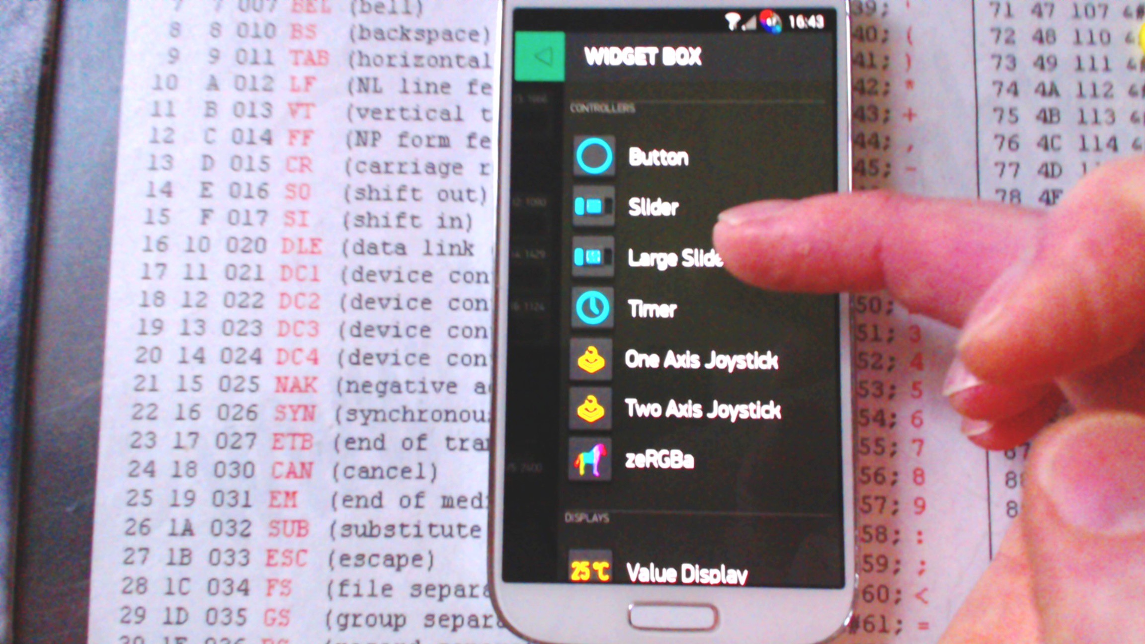
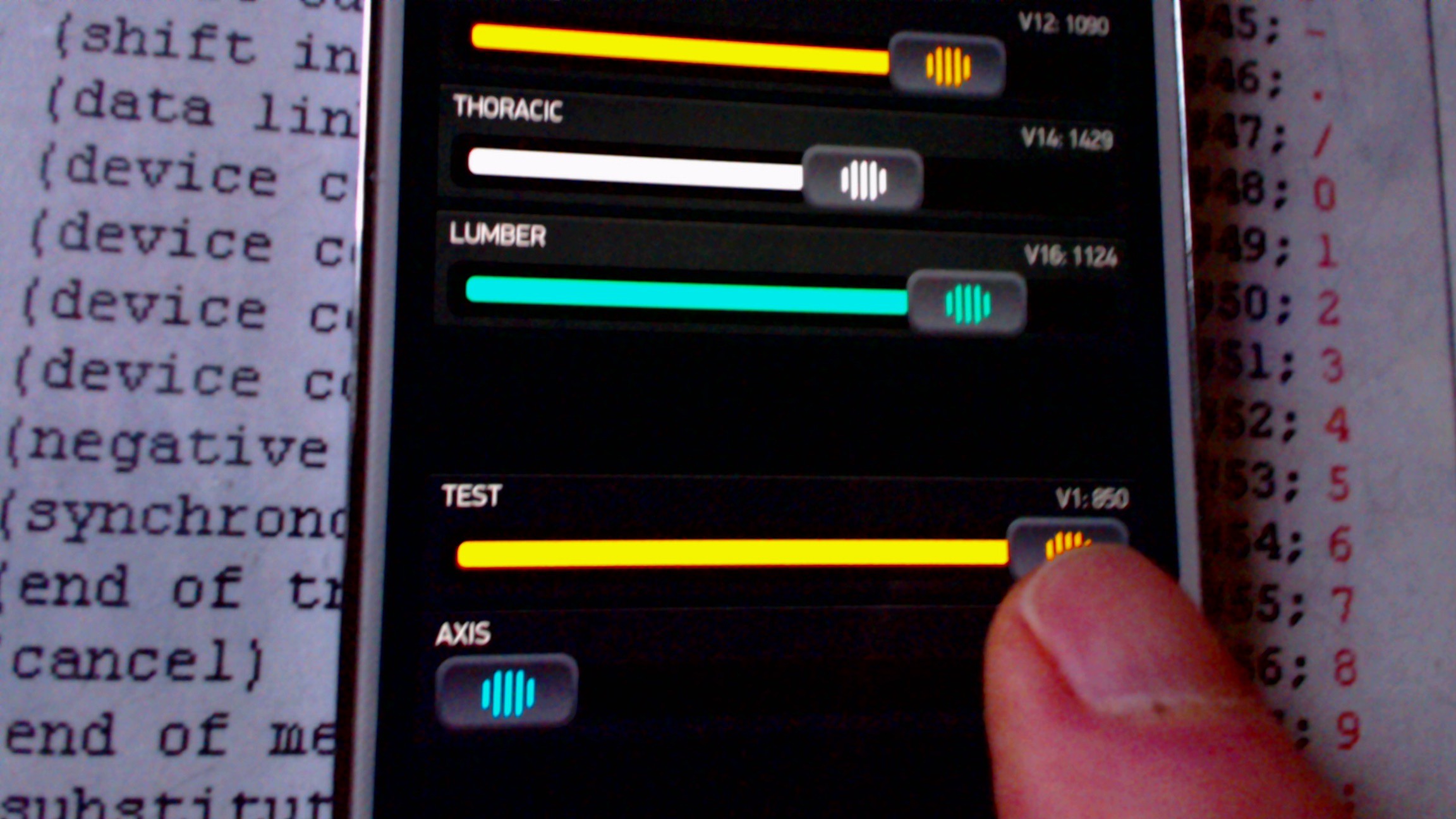
In our example we will set it up to control a Servo (5 actually) using an ESP8266 E12 WiFi chipset
So Select the "Large Slider" and this will be ported to your Project Gui.
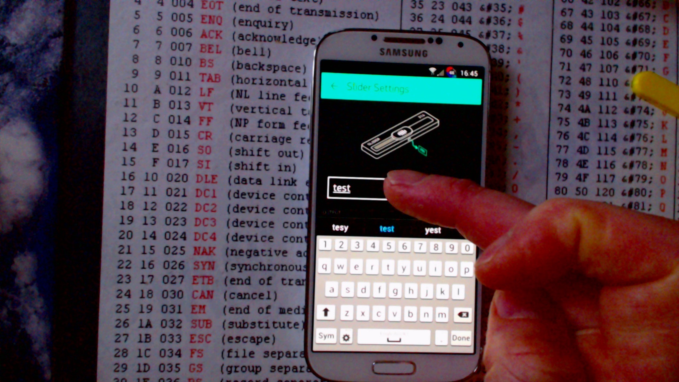
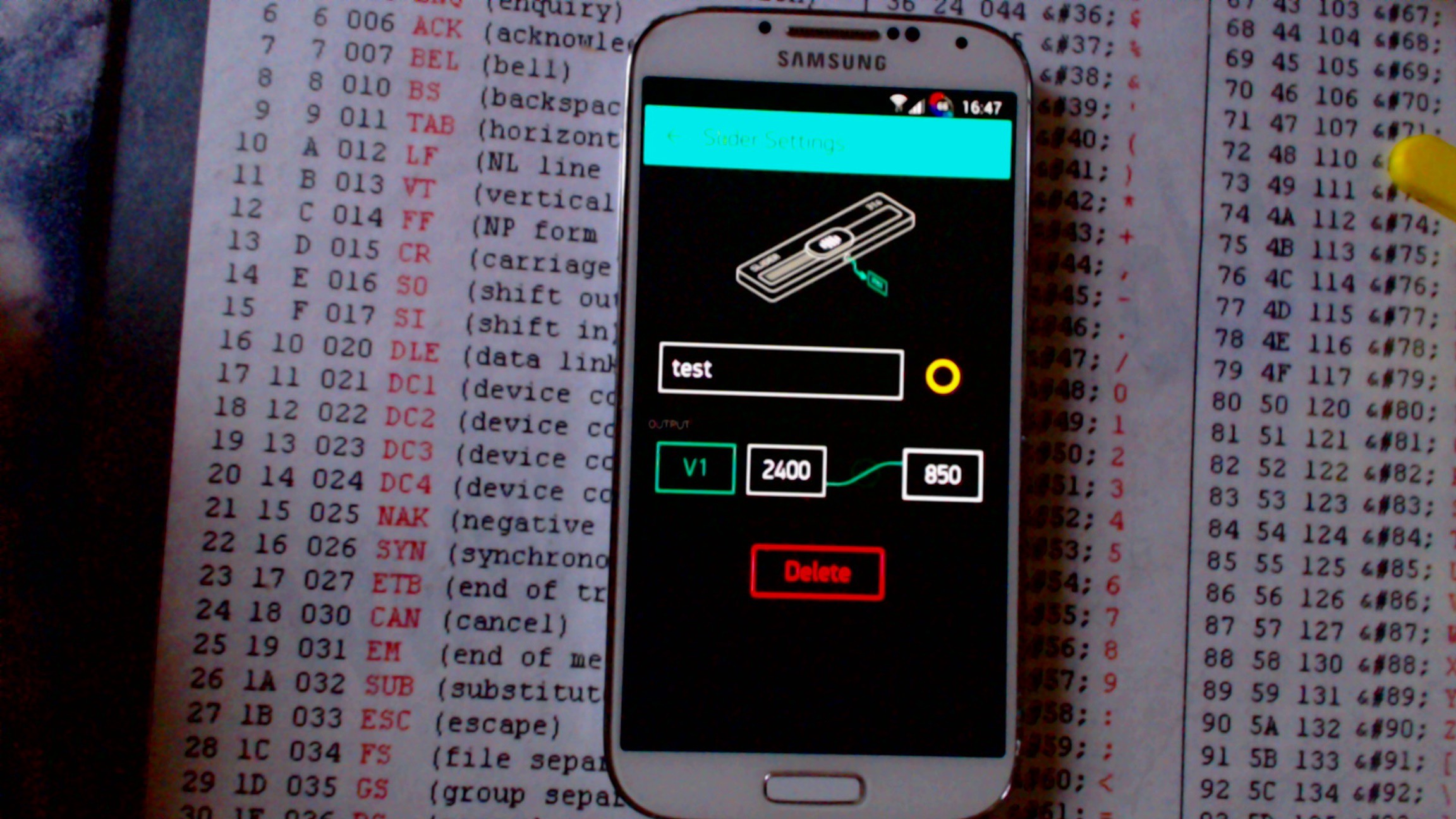
Press the slider and its setting will pop up .
Rename it.
On the "Output" press the greenbox (PIN) and Select "Virtual" and V15
Press the slider Setting bar to return to your Gui
That's the Smart Phone finished
On your Gui there will be a triangular ">" play button press this to run the module
PART 2
Now its time to load up your ESP8266 with some code.
I highly recommend you use the Arduino Gui to program the ESP8266 (it will save you a lot of heart ache)
You will need to place these libraries into your Arduino "libraries" folder :-
Blynk Libraries
Simple single ESP8266 Servo Code controlling servo on GPIO15
/*
* This sketch demonstrates how to scan WiFi networks.
* The API is almost the same as with the WiFi Shield library,
* the most obvious difference being the different file you need to include:
*/
#define BLYNK_PRINT Serial // Comment this out to disable prints and save space
#include <ESP8266WiFi.h>
#include <BlynkSimpleEsp8266.h>
#include <Servo.h>
// You should get Auth Token in the Blynk App.
// Go to the Project Settings (nut icon).
char auth[] = "place your Blynk authorisation code here ";
Servo servo;
void setup()
{
Serial.begin(9600);
Blynk.begin(auth, "WiFi Name", "Password"); // replace with your WiFi router details
servo.attach(15);
}
BLYNK_WRITE(V15)
{
servo.writeMicroseconds(param.asInt());
}
void loop()
{
Blynk.run();
}
Download the code to your ESP8266......
Be sure to connect your servo to Pin 15 of the ESP8266.
... and as your Smart Phone is already running you "Servo Gui" you can slider the slider to control the Servo.
If you notice I am using the servo.writeMicroseconds command servo values span 700-2300us.
NB. If you set the servo values 0 - 100 then the Blynk app will try to send 0microseconds or 100microseconds to the servo ....which is not recommended as the servo will try to disscombooberate its self.
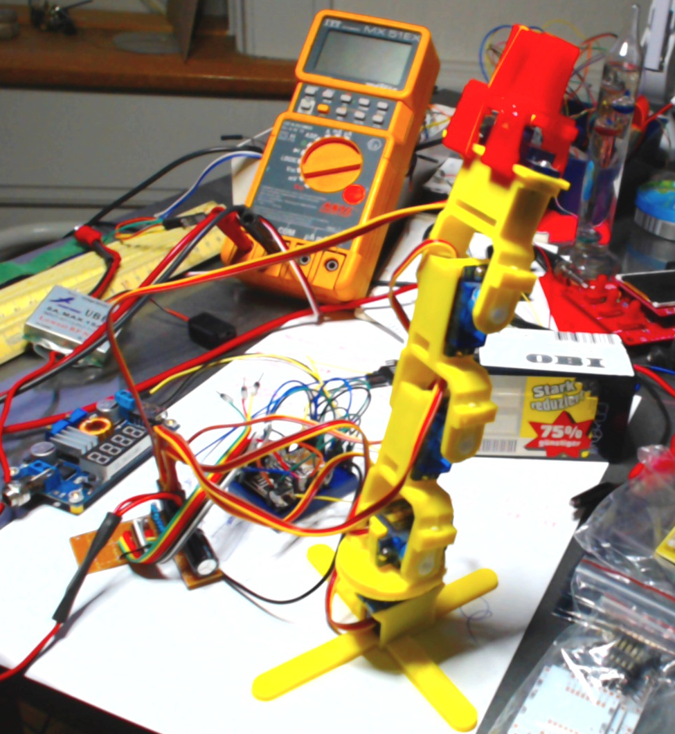
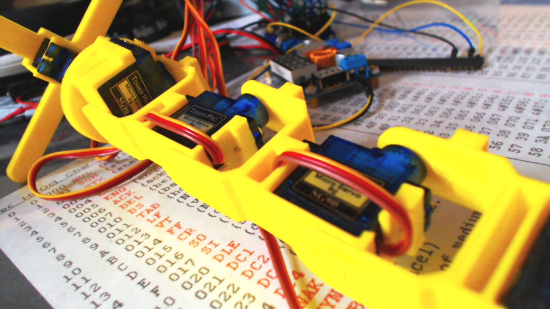
The Gripper arm is a simple chain of 3D printed servo holders.
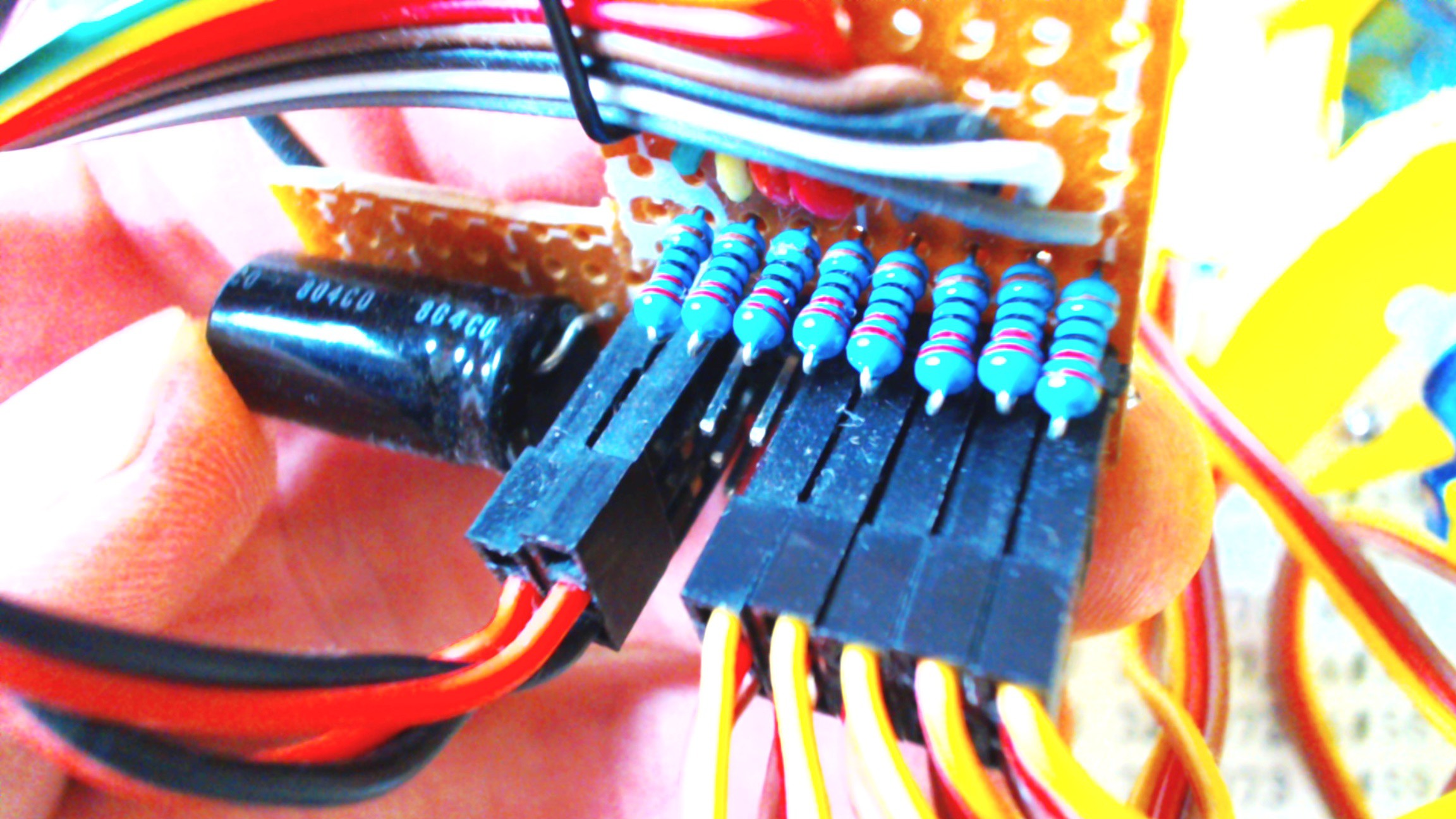
Things to consider are.....
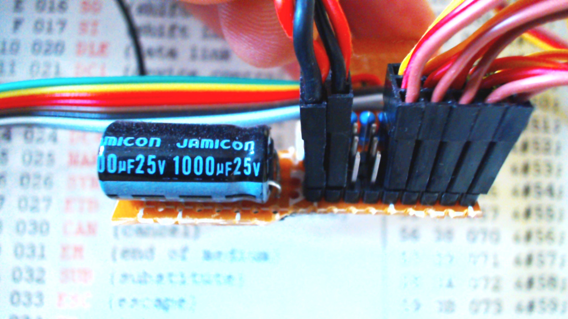
Use resistors on the PWM signal lines between the ESP8266 and the Servos
Do your self a favour and run the Servo Supply rails off a separate UBEC ... these supply mega amounts of current and can be easily switched for 5V or 6V servos.
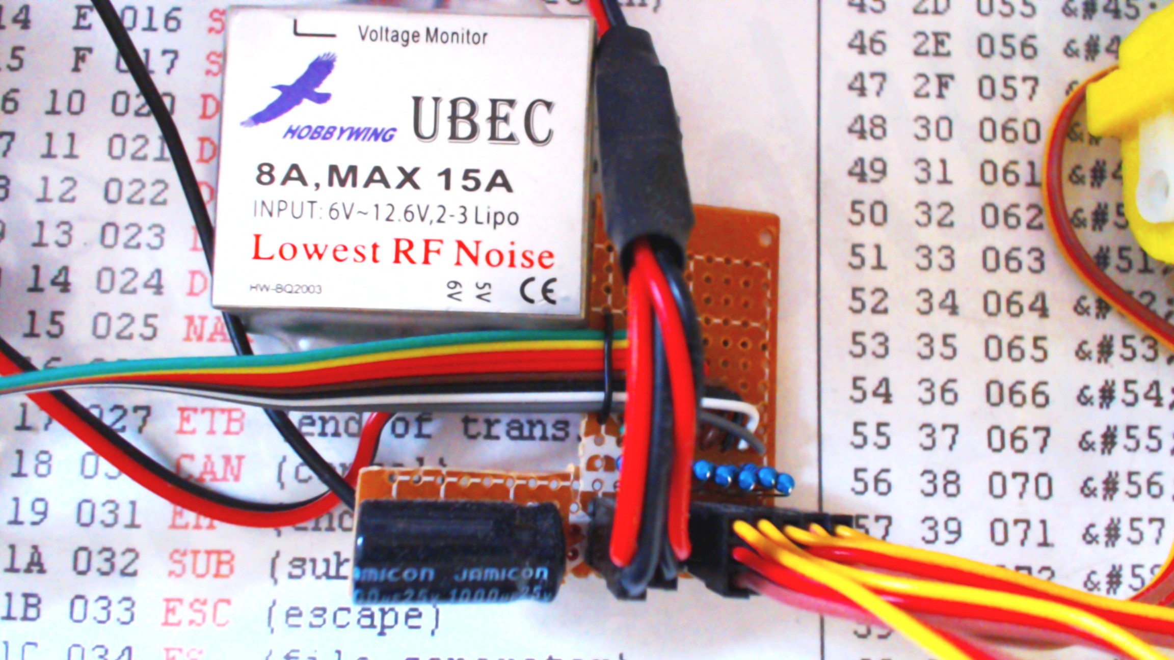
Place a beefy capacitor as close as possible to the servo plugs, this smooths out the current supply spikes off the supply rails and eliminates the any chance of the MCU browning out.